Operating Conditions
RF Transformers should always operate within safe limits of temperature and
linearity. Most amateur applications of matching transformers relate to baluns
in antenna systems, but they are also used as interstage or output transformers
in transmitters. Where possible windings should be made from suitable coax
cable. In some cases it is necessary to use twin line made from enamelled
copper wire (ecw) which has been spaced to achieve the desired line impedance.
EXCEL Programs which design HF toroid transformers can be downloaded from:
Programs. The following simple transformers using
toroid cores can be checked using these programs.
Simple Wire Wound HF Transformers For 50/75 Ohm Systems
The following diagrams and tables show some simple 1:1 and 4:1 baluns
for use between 1.8 and 30 MHz using twin transmission lines made from enamelled
copper wire (ecw). The baluns shown (except the current baluns) are voltage
(Ruthroff) baluns. The bifilar windings have been adjusted (spacing) to produce
transmission lines with Zo of 50 or 75 ohms as required for best matching.
These designs should be suitable for 100-200 Watt operation depending upon
operating mode.
Materials required:
- Ferrite Core: Select either rod or toroid core as detailed
below
- Core insulation: 1 layer of ptfe tape (plumbers thread
sealing tape); plumbing and hardware suppliers
- Wire: 1.0 or 1.25mm enamelled copper wire (ecw) as specified;
electronics shops
- Spacing material: Kinnears 540 TEX colourfil twine; product
code K 069048; newsagents, craft suppliers
Note: This spacing material is polypropylene; other
material is probably suitable, but ensure it will not absorb
moisture.
Winding Methods

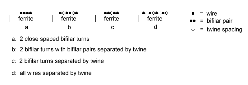
Examples of winding methods a, b, c, d on a rod.

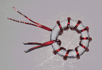
Toroid core with 10 close spaced bifilar turns
1:1 Rod Balun

Ferrite Rod: R-61-037-300
Construction:
Start by winding a layer of ptfe tape on the rod
Cut two 750mm lengths of 1.25mm ecw for a bifilar winding.
Starting at the centre of the rod, close wind half the length of
the wires towards one end. Repeat for the other half. 15 bifilar
turns (2 wires) should now be centred on the rod, with sufficient
end lengths for terminations.
Cut the spacing twine into 750mm lengths and insert between the
wires as required by tightly pulling the cord between the turns.
This makes a secure finished winding. Start at the centre of the
winding and work towards each end.
For a 50 ohm balun put spacing twine between the bifilar turns
(winding method c).
For a 75 ohm balun put spacing twine between all wires (winding
method d).
Waterproof, terminate and house the finished balun as
required.
See test results for the rod
balun.
4:1 Rod Balun

Ferrite Rod: R-61-037-300
Use the same winding method and materials as in the rod balun
above.
Construction:
Cut two 750mm lengths of 1.0mm ecw for a bifilar winding.
Wind 15 bifilar turns centred and close spaced on the rod.
Wind spacing twine between all turns as described above (winding
method d).
See test results for this rod
balun.
1:1 Toroid Balun

Ferrite Toroid: FT-140-61.
Use the same winding method and materials as in the rod balun
above.
Construction:
Spread the 12 bifilar turns of 1.25mm ecw evenly around the core.
This leaves space between the 12 turns.
If the lowest operating frequency is 3.5MHz then 10 turns is
sufficient.
For a 50 ohm balun the bifilar pairs are close spaced (winding
method a).
For a 75 ohm balun put spacing twine between the bifilar
pair(winding method b).
See test results for these toroid
baluns.
4:1 Toroid Balun

Ferrite Toroid: FT-140-61.
Use the same winding method and materials as in the rod balun
above.
Construction:
Spread the 12 bifilar turns of 1.25mm ecw evenly around the core.
This leaves space between the 12 turns.
If the lowest operating frequency is 3.5MHz then 10 turns is
sufficient.
For the 50:200 ohm balun the bifilar pairs are close spaced
(winding method a).
For the 75:300 ohm balun put spacing twine between the bifilar
pair (winding method b).
See test results for these toroid
baluns.
06/12/10
homepage


